起源
多旋翼的姿态控制中,\(roll\)和\(pitch\)的改变来自于旋翼提供的升力差实现,调整很快,十几毫秒就能到位,\(yaw\)的改变是通过改变旋翼产生的反扭距来调成,调整时间比较慢,要快100个毫秒才能就位。
问题描述
一般来说,多旋翼80%的能量用于抵抗重力,20%的能量用于控制姿态。当\(roll,pitch,yaw\)都有较大误差时,20%的能量被三个通道的控制器共同使用,而由于\(yaw\)响应较慢,会导致\(yaw\)的误差减小的比较慢,占用了更多用于姿态控制的能量,反而影响到整个姿态控制。
解决方式
因为旋翼飞行器稳定飞行的第一要求是桨平面的精确控制,也就是\(roll\)和\(pitch\),这两个角控不好飞机飞都飞不稳,相对来说,\(yaw\)是不是足够精确显得没有那么重要(毕竟机头朝向哪里都能飞)。那么在计算误差时,把误差分为两个部分,一部分是倾斜误差\(tilt\)(\(roll\)和\(pitch\)误差),一部分是旋转误差\(torsion\),然后对\(torsion\)做一些处理,比如限幅或者衰减,再重新合成一个总的姿态误差给控制器,这样,大部分姿态控制的能量用于\(roll\)和\(pitch\),有助于实现稳定飞行。
算法步骤
- 对齐当前机体坐标系z轴和期望机体坐标系z轴得到一个新的坐标系,获得tilt误差
- 把\(tilt\)误差转换到地理坐标系或者机体坐标系
- 总误差-\(tilt\)误差\(=torsion\)误差
- 限制\(torsion\)误差
- 把限制后的\(torsion\)误差和\(tilt\)误差合成新的误差作为总误差
基础知识
四元数
首先定义两个向量
- \(v_b\):某一个向量在机体坐标系下的坐标
- \(v_e\):同一个向量在地理坐标系下的坐标
那么旋转过程可以用下面的公式来表示:
\[ v_e = q_b^e \cdot v_b \cdot (q_b^e)^{-1} \]
这里,\(q_b^e\)就对应旋转矩阵中的\(C_b^e\)。
同时,四元数还遵循链式法则,比如某个向量连续进行了两次旋转,那么有
\[ q^3_1 = q^3_2 \cdot q^2_1 \]
注意 链式法则只有在同一坐标系下才是可以用的,比如机体坐标系,首先旋转了\(q1\),然后又旋转了\(q2\),那么总的旋转可以用\(q=q2 \cdot q1\)来表示,再转到地理坐标系下就是
\[ v_e = q2 \cdot (q1 \cdot v_b \cdot (q1)^{-1}) \cdot (q2)^{-1} = (q2 \cdot q1) \cdot v_b \cdot (q2 \cdot q1)^{-1} \]
旋转矩阵
先定义几个概念:当前坐标系下的一组单位正交基 \[ \begin{pmatrix} e_1 & e_2 & e_3 \end{pmatrix} \] 经过旋转后,新的坐标系下的单位正交基为 \[ \begin{pmatrix} e^{'}_1 & e^{'}_2 & e^{'}_3 \end{pmatrix} \] 对于同一向量\(a\),在两个坐标系下的坐标分别为 \[ \begin{pmatrix} a_1 & a_2 & a_3 \end{pmatrix}^T , \begin{pmatrix} a^{'}_1 & a^{'}_2 & a^{'}_3 \end{pmatrix}^T \]
那么通过基与坐标的关系可得 \[ \begin{pmatrix} e_1 & e_2 & e_3 \end{pmatrix} \cdot \begin{pmatrix} a_1 \\ a_2 \\ a_3 \end{pmatrix} = \begin{pmatrix} e^{'}_1 & e^{'}_2 & e^{'}_3 \end{pmatrix} \cdot \begin{pmatrix} a^{'}_1 \\ a^{'}_2 \\ a^{'}_3 \end{pmatrix} \]
等式两边左乘 \[ \begin{pmatrix} e_1^T & e_2^T & e_3^T \end{pmatrix}^T \]
可以得到 \[ \begin{pmatrix} a_1 \\ a_2 \\ a_3 \end{pmatrix} = \begin{pmatrix} e_1^Te^{'}_1 & e_1^Te^{'}_2 & e_1^Te^{'}_3 \\ e_2^Te^{'}_1 & e_2^Te^{'}_2 & e_2^Te^{'}_3 \\ e_3^Te^{'}_1 & e_3^Te^{'}_2 & e_3^Te^{'}_3 \end{pmatrix} \cdot \begin{pmatrix} a^{'}_1 \\ a^{'}_2 \\ a^{'}_3 \end{pmatrix} \]
现在让我们回忆一下向量内积

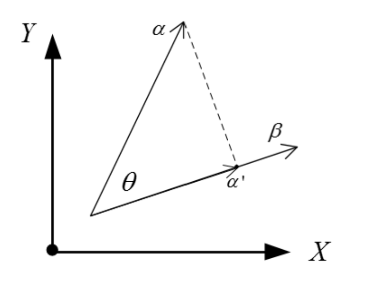
对于两个向量\(e_1\)和\(e^{'}_1\),他们的内积\((e^{'}_1,e_1)=e^T_1\cdot e^{'}_1\),而他们的几何意义可以看成\(e^{'}_1\)在\(e_1\)方向上投影的模再乘\(e_1\)本身的模,\(e_1\)又是单位向量,模值为1,所以再这种情况下,\(e^T_1\cdot e^{'}_1\)的值就等于\(e^{'}_1\)在\(e_1\)方向上投影的模。
观察旋转矩阵,可以发现旋转矩阵的每一列都是旋转后的坐标系下的基在原坐标系下的基的投影分量,放到姿态解算这个问题上来,设地理坐标系为北东地(NED)坐标系,各xyz坐标轴上的单位向量为一组基,那么旋转过后的坐标系,也就是机体坐标系,这两个坐标系之间的旋转矩阵的第一列代表机体坐标系下的x轴在地理坐标系xyz轴上各轴的分量,也可以理解为坐标,第二列表示机体坐标系下y轴在地理坐标系xyz轴上各轴的分量,以此类推。
PX4的倾转分离实现
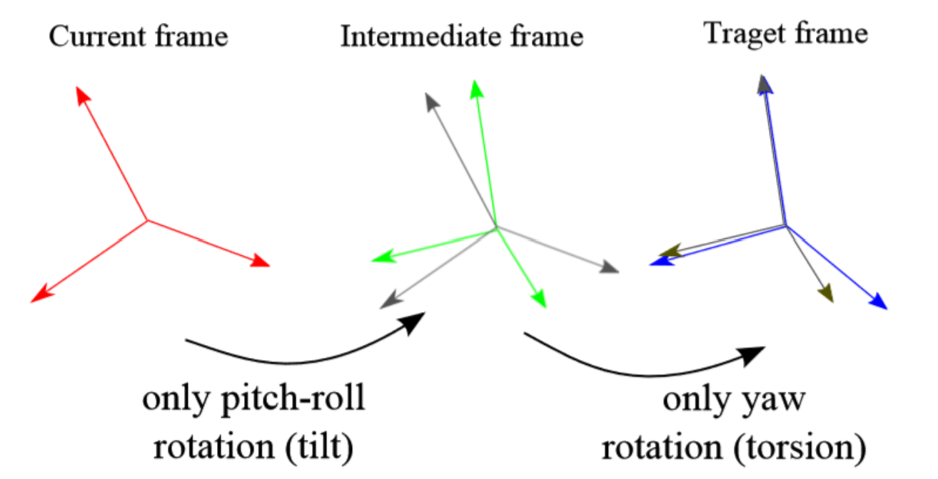
根据上面的算法我们知道,在当前机体坐标系转到期望机体坐标系之前,首先要得到一个中间坐标系,这个坐标系将当前的机体坐标系和期望机体坐标系的z轴进行了对齐,但是保留了\(yaw\)的误差,就像下图所示。

可以看到,中间坐标系(灰色)和期望坐标系(蓝色)的区别仅仅是z轴的旋转。那么首先就要获得这个中间坐标系。
在PX4的姿态控制代码中,首先获得了当前姿态和期望姿态的四元数\(q^{N}_{cur}\)和\(q^{N}_{tar}\) 然后把当前姿态和期望姿态的z轴向量提取出来,也就是先转换成旋转矩阵,根据上面旋转矩阵得出的结论可以知道,旋转矩阵的第三列就是机体坐标系z轴在地理坐标系下对应的向量坐标。
得到了两个向量,可以通过这两个向量,构造出旋转四元数\(q_{red}\),注意这里的旋转四元数是在地理坐标系下构建的,不能用于链式法则。或者说,这个四元数应该长成这样:
\[ [q^{cur}_{half}]^N \]
换句话说,这个四元数是在地理坐标系下看到的当前坐标系与中间坐标系之间的误差。因此要先将其转换到机体坐标系下。根据公式,有
\[ [q^{cur}_{half}]^N=(q^{N}_{cur}) \cdot q^{cur}_{half} \cdot (q^{N}_{cur})^{-1} \]
得到
\[ q^{cur}_{half}=(q^{N}_{cur})^{-1} \cdot [q^{cur}_{half}]^N \cdot (q^{N}_{cur}) \]
转到机体坐标系下后就可以用链式法则了。中间坐标系到地理坐标系的旋转四元数为
\[ q^{N}_{half}=q^{N}_{cur} \cdot q_{half}^{cur} = q^{N}_{cur} \cdot (q^{N}_{cur})^{-1} \cdot [q^{cur}_{half}]^N \cdot (q^{N}_{cur}) = [q^{cur}_{half}]^N \cdot (q^{N}_{cur}) \]
这样就得到中间坐标系的旋转四元数了。下一步是得到旋转误差\(torsion\)四元数,这个四元数就是把中间坐标系旋转到目标坐标系,我们把它叫\(q_{tar}^{half}\)。由链式法则可以得到
\[ q_{tar}^{half}=q_{N}^{half} \cdot q_{tar}^{N} = (q_{half}^{N})^{-1} \cdot q_{tar}^{N} \]
这个四元数就表征了\(yaw\)误差的大小,根据轴角定义可得,这个四元数正常来说应该长这样:
\[ q_{tar}^{half}=(\cos{\theta/2},0,0,\sin{\theta/2 \cdot z}) \]
\(\theta\)就是要转的\(yaw\),也就是\(yaw\)轴误差。我们可以对这个误差进行限幅或者衰减。
最后,把衰减后的旋转误差四元数和倾斜误差四元数合成,得到新的期望四元数
\[ q_{tar}^{N} = q^{N}_{half} \cdot q_{tar}^{half} \]
接下来,获得总的误差四元数
\[ q_{tar}^{N} = q^{N}_{cur} \cdot q^{cur}_{tar}, \\ q_{e} = q^{cur}_{tar} = (q^{N}_{cur})^{-1} \cdot q_{tar}^{N} \]
至此,倾转分离完成。
PX4相关部分的代码实现:
1 | matrix::Vector3f AttitudeControl::update(const Quatf &q) const |
仿真验证
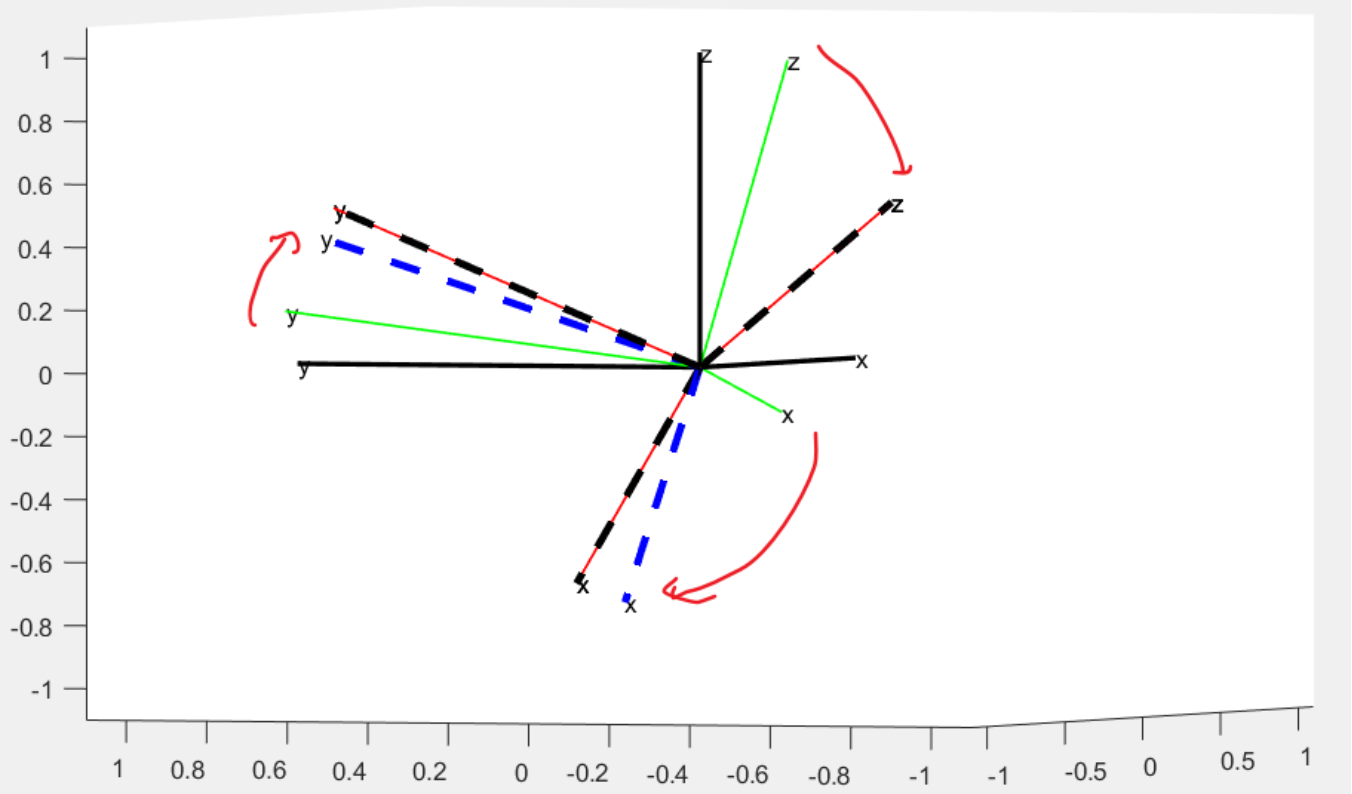
贴几张网上的博主关于此部分的matlab代码验证。
 图中绿色坐标系为当前机体坐标系,红色坐标系为期望机体坐标系
黑色虚线为不进行「倾转分离」时的旋转,那么得到的误差,可以让坐标系完全重合。
蓝色虚线为「倾转分离」后计算的旋转,只能保证z重合,即roll 和 pitch
没有误差。
总结
通过倾转分离,有效的对\(yaw\)轴误差进行了限制,有利于控制器分配更多的能量用于更加关键的\(pitch\)和\(roll\)控制,实际上就是把倾斜的控制优先级提高了。


